If you are sitting on a folder of drone photos and wondering how to turn them into a georeferenced 3D model for use in Swyvl or Cesium JS, this is for you. This tutorial walks through the full workflow using RealityCapture and a public sample dataset with ground control points (GCPs). We’ll cover everything from image import to 3D Tiles export, plus tips for working with ground control points (GCPs) or using RTK drones instead.
We’ve tested this exact workflow to build lightweight, accurate models that load beautifully in Swyvl.
What You’ll Need
For this tutorial, you can use your own dataset or use the sample dataset from Reality Capture. The sample dataset includes 482 images captured by a DJI Phantom 4 Pro, with GPS metadata embedded in the EXIF data (i.e. it's got everything you need for this tutorial). This sample dataset (Drone Imagery) and others are available on the RealityCapture Sample Datasets page.

Whether you are using your own data or the sample data, before we dive in, make sure you have the following:
- Drone imagery: High-quality images with sufficient overlap (70–80% side, 60–70% forward).
- Ground Control Points (GCPs): Provided in a .txt file with at least 13 GCPs in WGS84 (EPSG:4326), defining latitude, longitude and height.
Example:101 49.029540967 18.290611333 249.071
102 49.029209987 18.290071979 249.000
... - GCP Image Assignments: A .csv file with pixel coordinates linking each GCP to specific images.
Example:DJI_0316.JPG, 101, 1772.00, 405.04
DJI_0317.JPG, 101, 1790.92, 872.09
... - RealityCapture Software: A licensed version that supports Cesium 3D Tiles export.
Step-by-Step Drone Photogrammetry Process Using the GCP Drone Sample Dataset
1. Download and Prepare the GCP Drone Sample Dataset
- Download the sample dataset here
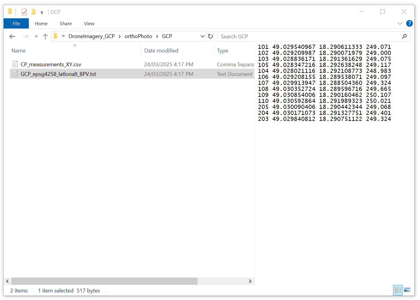
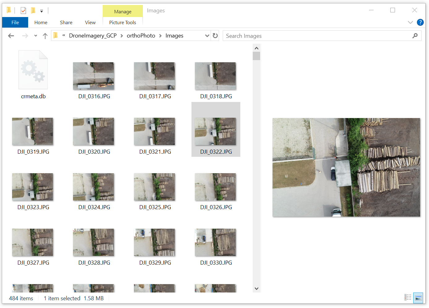
- Extract the .zip file to a local folder. The folder includes:
- 483 JPEG drone images (DJI Phantom 4 Pro)
- A .txt file (GCP_epsg4258_latlonalt_BPV.txt) with GCP coordinates
- A .csv (CP_measurements_XY.csv) with image-to-GCP pixel assignments
Tip: For your own drone data, capture in good lighting (avoid harsh shadows or overexposure) and maintain sufficient overlap (70-80% side, 60-70% forward) to prevent gaps in the 3D model.
2. Collect GCP Data (For Your Own Projects)
Since the sample dataset includes GCPs, this step is for users collecting their own data:
- Place Markers: Use visible markers like painted crosses or survey markers, large enough to be clearly visible in the drone images (e.g, 30x30cm for a 50m flight altitude)
- Measure Coordinates: Use a high-precision GPS receiver (e.g. a survey-grade GNSS device) to record the coordinates of each marker in WGS84 (latitude, longitude, height). Aim for sub-centimeter accuracy if possible.
- Record in a .txt File: Format the data as shown in the provided .txt file
ID, Latitude, Longitude, Height
101 49.029540967 18.290611333 249.071
...
Tip: Distribute GCPs evenly across the area, with at least 5-10 points for a small site. Place them in areas with good visibility from multiple angles to ensure they appear in several images.
3. Alternative: Using an RTK Drone
RTK (Real-Time Kinematic) drones embed centimetre-accurate GPS data in image metadata.
RTK reduces processing time and effort, but requires a compatible drone and base station setup.

With RTK, you can often skip GCP import and assignment - but you should still set the coordinate system to WGS84 in RealityCapture and verify accuracy.
Tip: Even with RTK, consider using a few GCPs as checkpoints to validate accuracy, especially for large or critical projects. For the sample dataset, GCPs are necessary since it was captured with a non-RTK drone (DJI Phantom 4 Pro).
4. Import Drone Imagery into RealityCapture
- Open RealityCapture and create a new project.
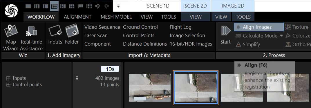
- In the Workflow tab, under 1. Add Imagery, select Inputs and import the 149 images from the sample dataset.
- The GPS metadata will assist in initial alignment.

Tip: For large datasets, ensure your computer has sufficient RAM and GPU power (e.g. 32GB RAM, NVIDIA GPU) to handle processing efficiently.
5. Import and Assign Ground Control Points
Import GCP Coordinates
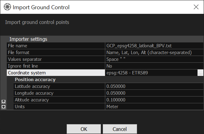
In the 1Ds view, select Ground Control from the Import & Metadata section and load the provided .txt file with 13 GCPs. This file contains the WGS84 coordinates (latitude, longitude, height) for each GCP.

An Import Ground Control prompt will show, ensure that epsg:4258 - ETRS89 is chosen as the Coordinate system. Then press OK.
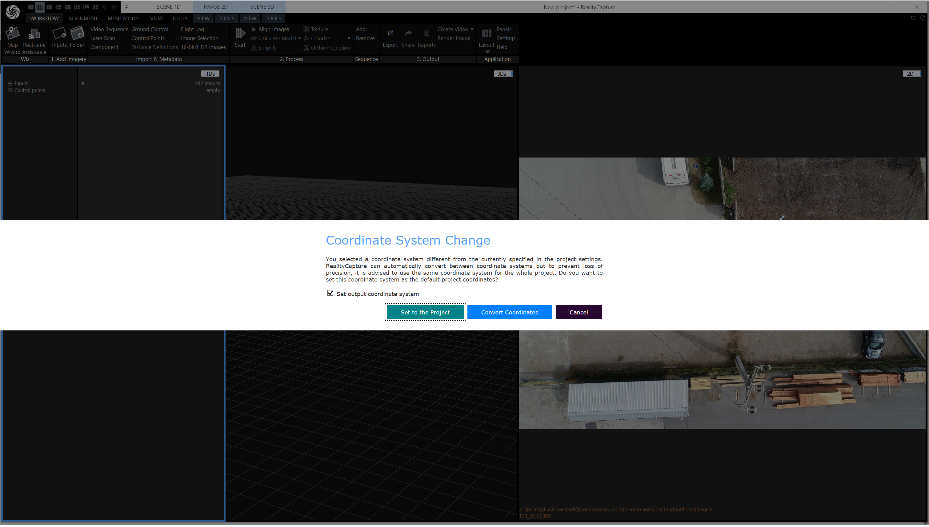
A popup will appear. Select Convert Coordinates.
Import GCP Image Assignments
In the 1Ds view, select Control Points from the Import & Metadata section and load the provided .csv file. This file automatically assigns each GCP to its pixel locations in the images, saving significant time.
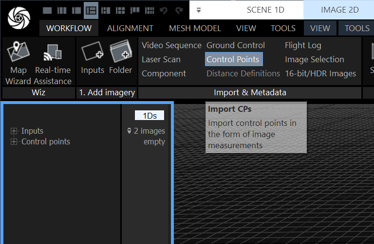
The .csv file links each GCP to multiple images (e.g. GCP 101 is assigned to 20 images like DJI_0316.JPG at pixel coordinates 1772.00, 405.04). Leave the default settings and press OK.

Verify Assignments
Switch to the 2Ds view to review the assignments. RealityCapture will display the marked locations of GCPs in the images. Check a few assignments (e.g. GCP 101 in DJI_0316.JPG) to ensure accuracy, and adjust manually if needed.
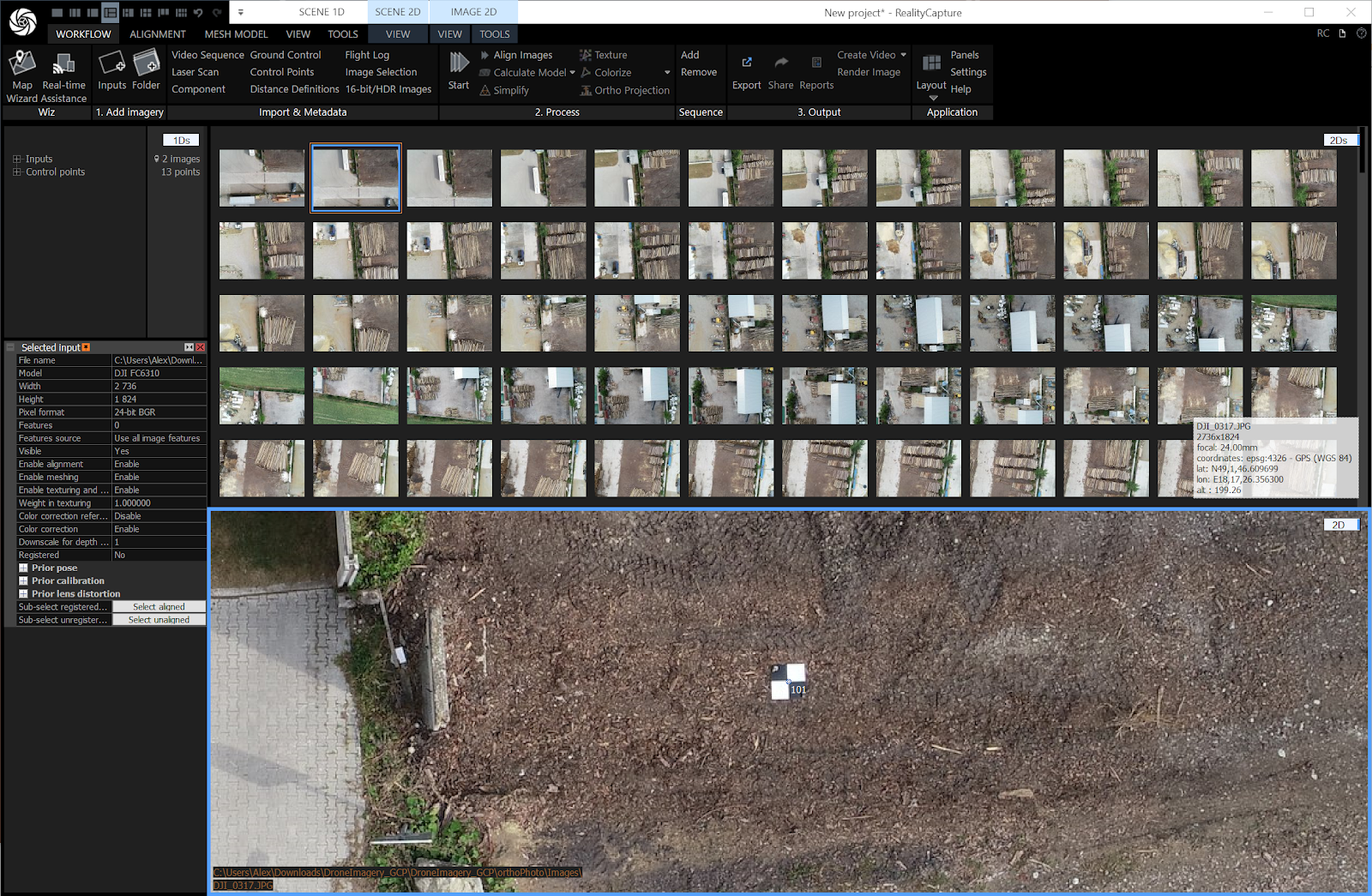
Tip: The .csv file automates a tedious step, but if any assignments are incorrect (e.g. due to image distortion), you can manually adjust the pixel coordinates in the 2Ds view. Zoom in on the images to ensure precise placement.
6. Set the Coordinate System to WGS84
Select Settings from the Application section.
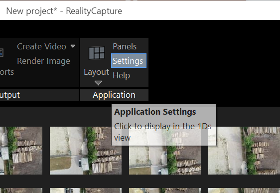
From the Application Settings, expand the Coordinate Systems section and select EPSG:4326 - GPS (WGS 84)
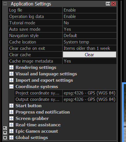
7. Align Images
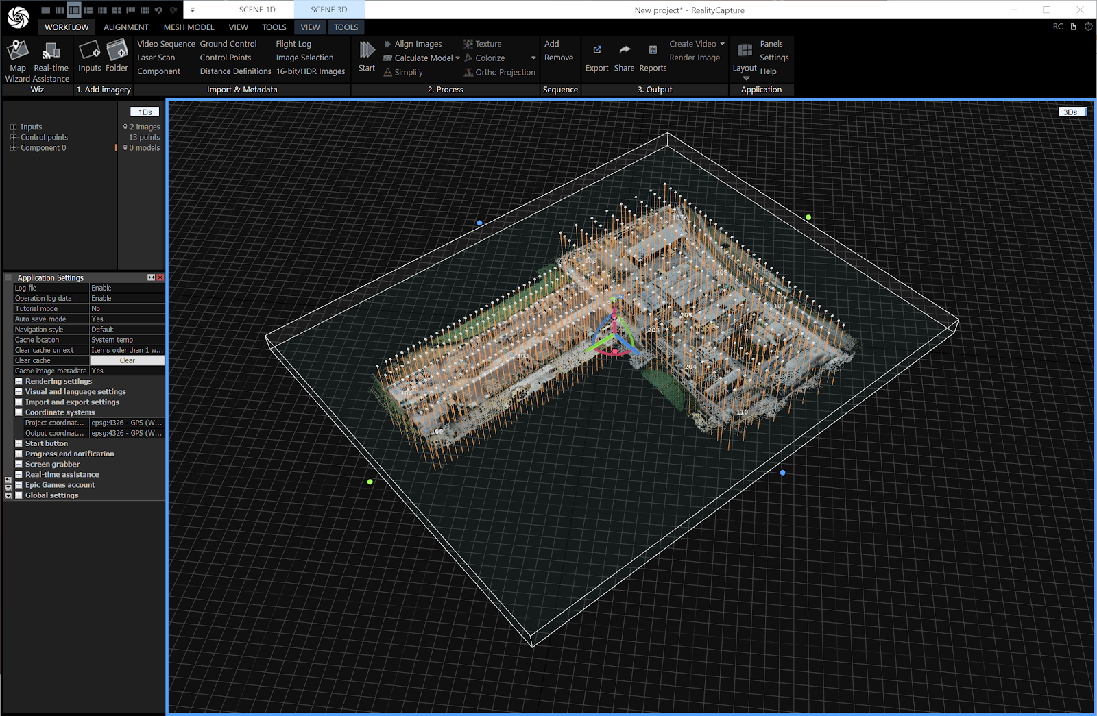
In the Workflow tab, in the 2. Process section, select Align Images. RealityCapture uses the image content, GPS metadata, and GCPs (or RTK data) to compute accurate camera positions and scene geometry.

You will notice the bounding box cuts through the point cloud. Click on the model to enable it, and then rotate using the red orbit tool and adjust size using the colored grab circles at the edges.

8. Build the 3D Mesh
In the Workflow tab, in the 2. Process section, select Calculate Model and then click Normal quality to generate the 3D mesh from the aligned point cloud.
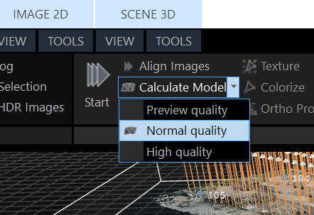
For the sample dataset, the resulting mesh should be relatively small and manageable. For larger datasets, consider simplifying the mesh to optimize performance in Swyvl if you notice performance decreases.


9. Colorize and Texture the Model
Colorize the Model
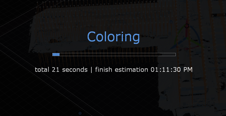
In the Workflow tab, in the Process section, select Colorize and then click Normal quality.
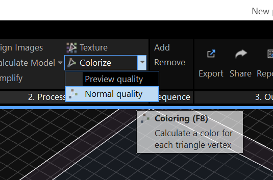
RealityCapture automatically calculates vertex colors using the aligned images. This step enhances visual quality for the sample dataset’s dense mesh but is insufficient alone for Cesium 3D Tiles export.
Texture the Model
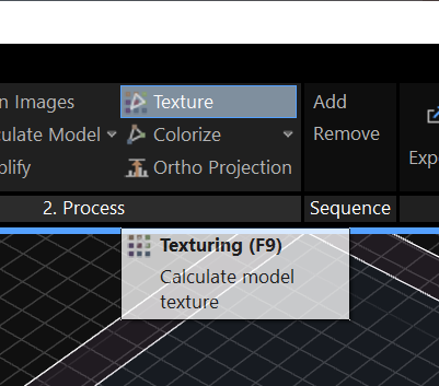
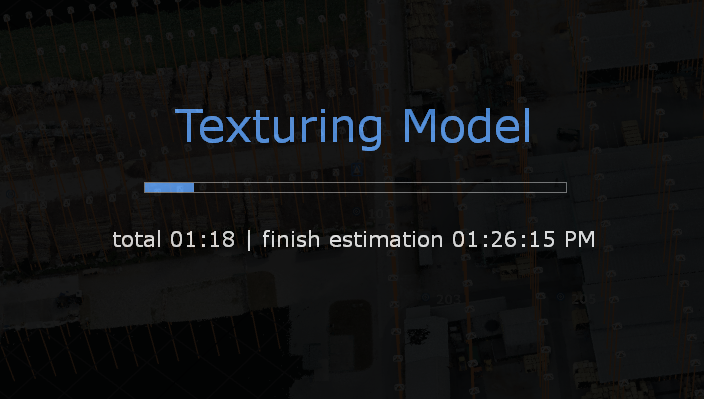
In the Workflow tab, in the 2. Process section, select Texture.
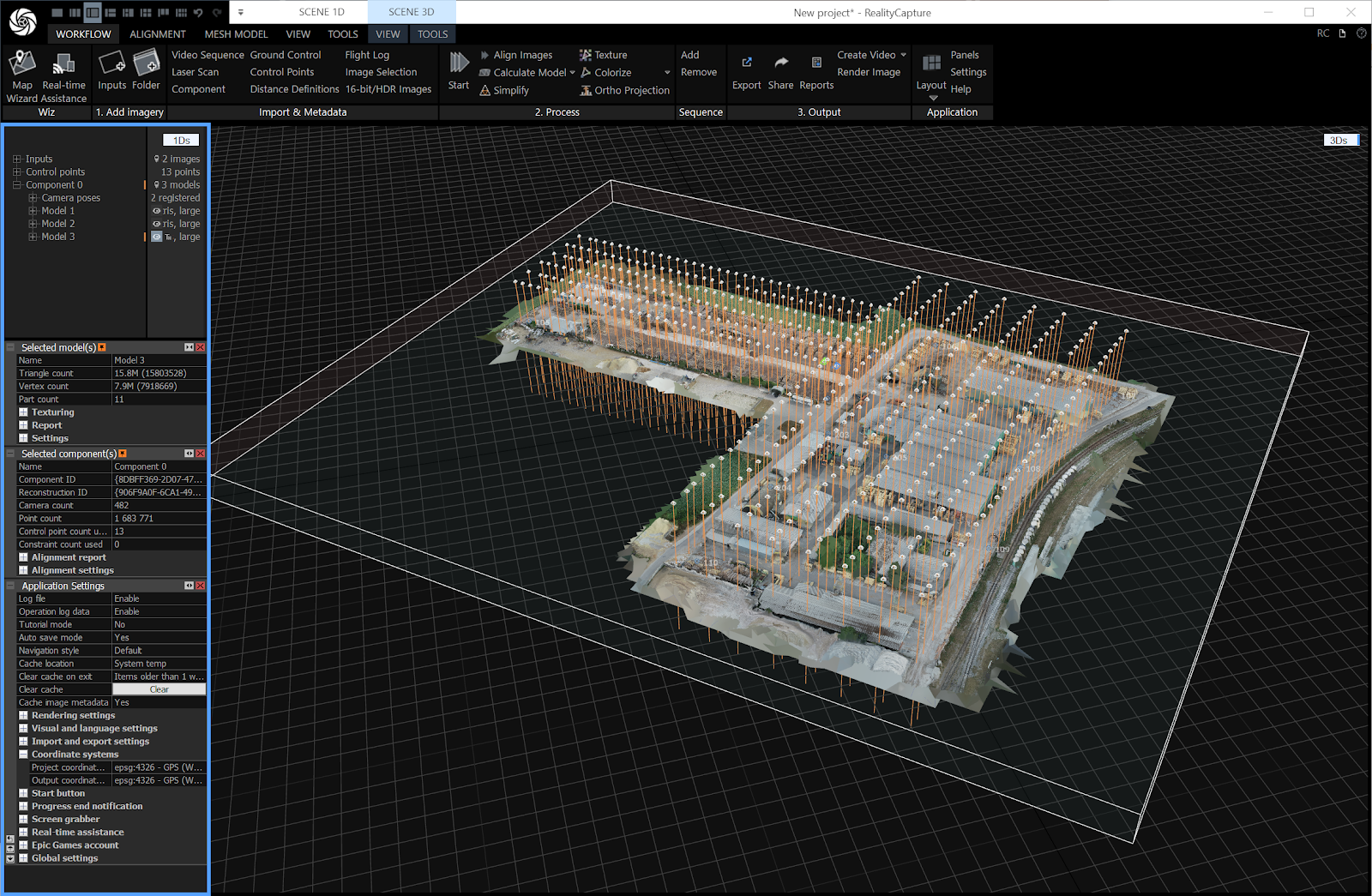
After processing, verify the texture in the 3D view to ensure it looks correct, with no stretching or artifacts.
10. Export as Cesium 3D Tiles
Open Export Options
In the Workflow tab, in the 3. Output section, select Export.

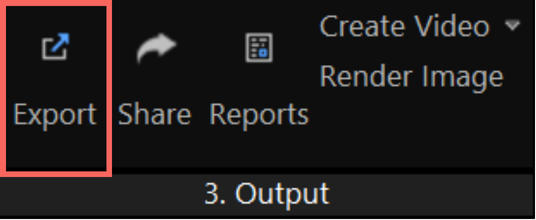
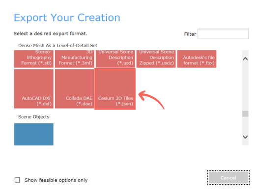
Select Cesium 3D Tiles from the popup.
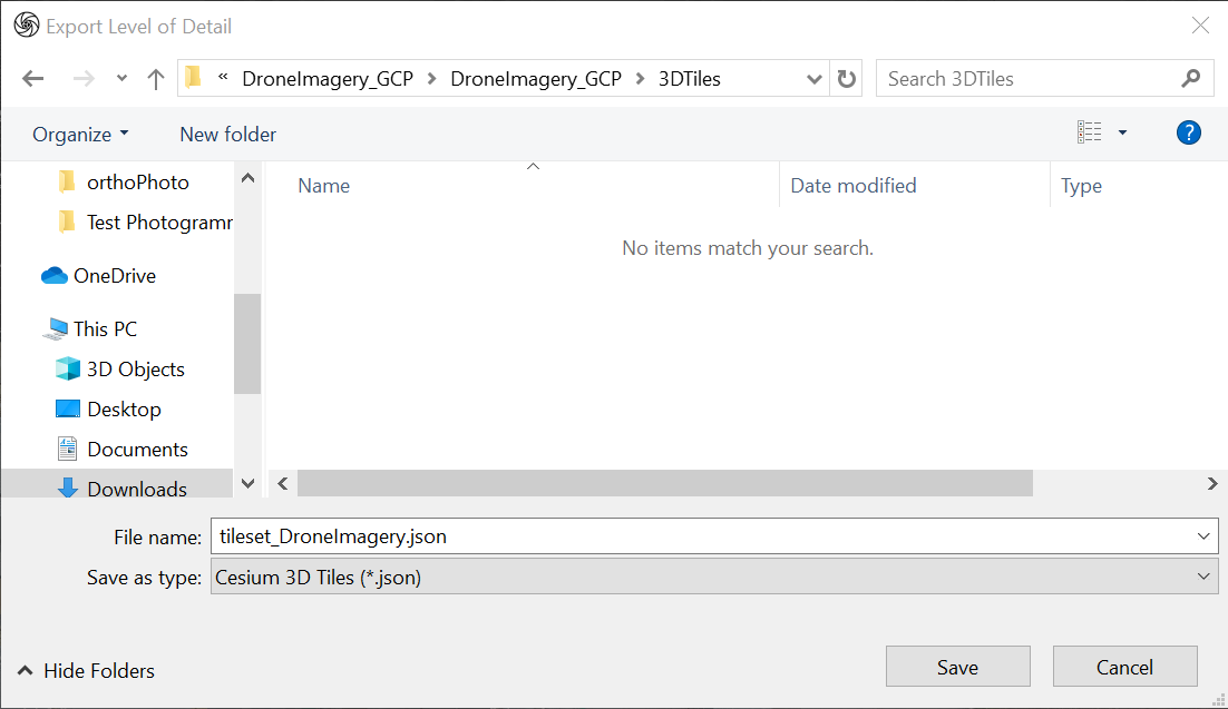
Choose the folder location you want to save the Cesium 3D Tileset.
Alternative method: Go to SCENE 3D > TOOLS, then under Export, select Levels of Detail.
Configure Export Settings for Cesium 3D Tiles (Critical - Do not skip this step!)
The right settings make all the difference. Here’s what works well for most scenarios and why each setting matters:
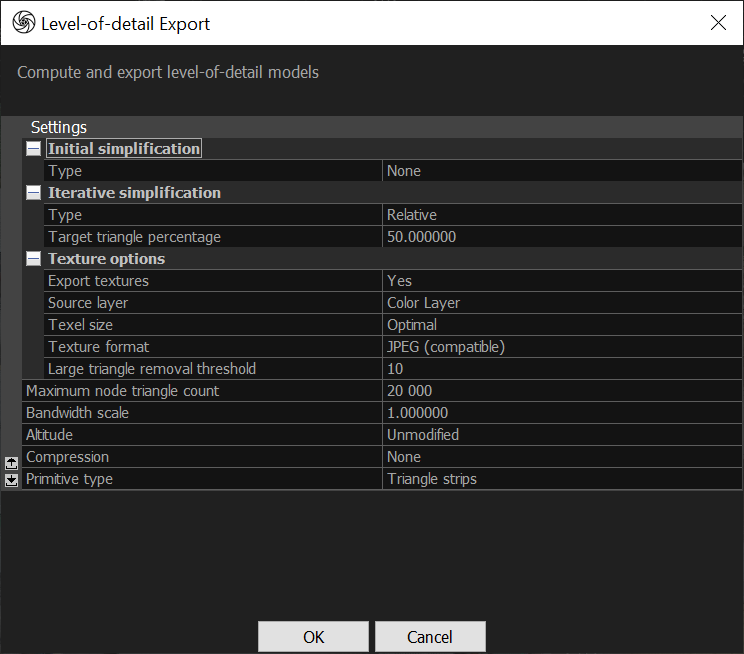
- Initial Simplification:
- Type: None (Retains original detail)
- Iterative Simplification:
- Type: Relative
- Target Triangle Percentage: 50% (This reduces the polygon count by 50%, balancing detail and performance for web streaming)
- NB: Too little simplification causes slow loading; too much reduces visual quality. A 50% reduction often hits the mark.
- Texture Options:
- Export Textures: Yes (textures are required for Cesium 3D Tiles and give visual detail)
- Source Layer: Color Layer (ensures accurate textures)
- Texture Size: Optimal (RealityCapture selects ideal resolution, typically 4K to ensure file quality without excessive file size
- Texture Format: JPEG (compatible) (JPEG provides good compression for web use, reducing file size while maintaining visual quality)
- Large triangle removal threshold: 10
- Maximum Node Triangle Count: 20,000 (this ensures the tiles are small enough for efficient streaming of Cesium 3D Tiles)
- Bandwidth Scale: 1.0 (this default setting is appropriate for general use, as CesiumJS handles its own compression (e.g. KTX 2.0) during rendering
- Altitude: Unmodified (suitable for models georeferenced in WGS84).
- Compression: None
- Primitive Type: Triangle Strips (this format is widely supported and optimized for CesiumJS rendering).
Start Exporting Cesium 3D Tiles
- Click OK to initiate the export.
- RealityCapture will generate your Cesium 3D Tileset (multiple files), including a tileset.json file, saved in your selected folder.
Depending on your model size, this is the optimal time to grab a coffee (or two!) while you wait for the files to export.
After Exporting Cesium 3D Tiles from RealityCapture
Prepare Files for Upload
- Locate the folder containing your exported Cesium 3D Tileset.
- Compress the entire folder, including the tileset.json, into a single .zip file.

Upload Cesium 3D Tiles to Swyvl
- Log in to your Swyvl account or sign up for a 14 day free trial.
- Create a new project or open an existing one.
- In the Toolbar, select 3D Data, then 3D Tileset and upload your zipped Cesium 3D Tiles.
Verify the Upload in Swyvl
- Confirm your Cesium 3D Tiles display correctly in Swyvl.
- Use the Fly To button [icon] in the Project Data Sidebar to zoom directly to your 3D Tileset and verify texture accuracy and proper georeferencing.
These steps are specific to Swyvl, but a similar workflow applies to other platforms like CesiumJS—export, host, and visualise your 3D Tiles with minor adjustments depending on the platform.
Additional Tips
Image Quality with Drone Data
The sample dataset has good overlap and lighting, but for your own projects, avoid flying during midday when harsh shadows can affect texture quality. Early morning or late afternoon light is ideal.
GCP Collection Best Practices
When collecting GCPs, ensure markers are securely placed and won’t move during the flight. Use a GNSS receiver with RTK capabilities for higher accuracy, and record heights relative to the WGS84 ellipsoid (not geoid) to match CesiumJS expectations.
RTK vs. GCPs
If you're using an RTK drone, processing is faster since you can skip the GCP assignment step. But it's still good practice to verify the accuracy of RTK data against known points. For the sample dataset, GCPs are necessary since it was captured with a non-RTK drone (DJI Phantom 4 Pro).
Using the .csv File
The provided .csv file automates GCP assignment, which is especially helpful for the sample dataset with 149 images. Without it, manually assigning 13 GCPs to multiple images would be time-consuming.
Optimize File Size
The sample dataset is relatively small, but for larger projects, you may want to reduce the texture resolution (e.g. to 2K) or simplify the mesh further if performance in Swyvl starts to drop.
Performance in Swyvl
The recommended export settings—50% triangle reduction and 20,000 triangles per node—work well for the sample dataset. For larger models, it's worth testing performance in Swyvl and adjusting settings if needed.
Validate Georeferencing
After uploading, confirm that the model’s position in Swyvl matches the expected WGS84 coordinates. For the sample dataset, this should be close to 49.03, 18.29. If it’s off, double-check the coordinate system settings in RealityCapture.
By following this process, you’ll successfully create a georeferenced 3D model from the GCP Drone Sample Dataset using RealityCapture and export it as Cesium 3D Tiles for use in Swyvl.
For further troubleshooting, refer to RealityCapture’s documentation or Swyvl support resources.


.jpg)


